Blog
- Home
- Blog
Jib Crane Column Foundation Design : Specifications for Bolts and Concrete
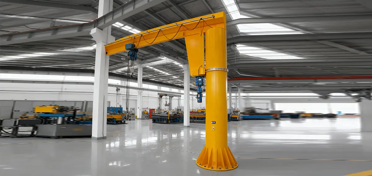
In industrial plants and production lines, the jib crane is widely used due to its small footprint and flexibility. It relies on a single column to support the cantilever and rated load. Its structural characteristics determine that the column bottom withstands extreme bending moments, axial tension, and shear forces. Therefore, the reasonable design of the jib crane column foundation directly affects installation stability. It also ensures long-term safe operation. This article deeply analyzes the design essentials of the jib crane column foundation from three core dimensions. These include foundation bearing capacity calculation principles, concrete foundation design requirements, and anchor bolt selection and embedment specifications.
Stress Analysis and Principles of Jib Crane Foundation Design
The design of the jib crane column foundation cannot be estimated solely by the total equipment weight. It must focus on compound stress states under the worst working conditions.
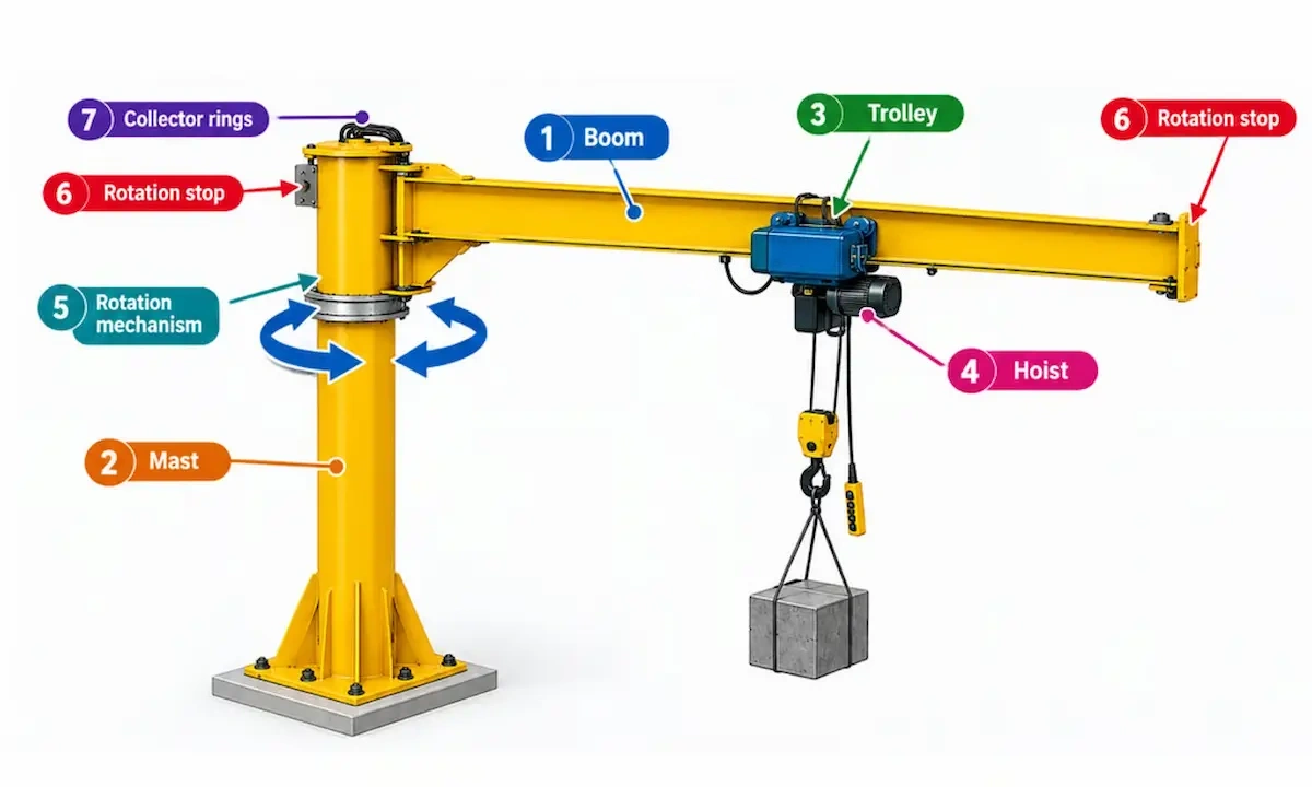
●Maximum Overturning Bending Moment (M): It is generated by multiplying the rated capacity by the maximum working radius. This moment acts as the main control factor in foundation design.
●Vertical Axial Force (Fz): This includes the crane self-weight, rated lifting load, and additional forces from dynamic load coefficients.
●Horizontal Shear Force (Fx/Fy): This is caused by inertial forces from slewing mechanism start/stop and horizontal push forces from trolley operation.
The foundation base area and mass must ensure an anti-overturning safety factor of at least 1.5 to 2.0. At the same time, the bearing layer compressive stress must remain below the allowable bearing capacity. This prevents uneven settlement from causing column tilting.
Concrete Foundation Design Requirements and Construction Specifications
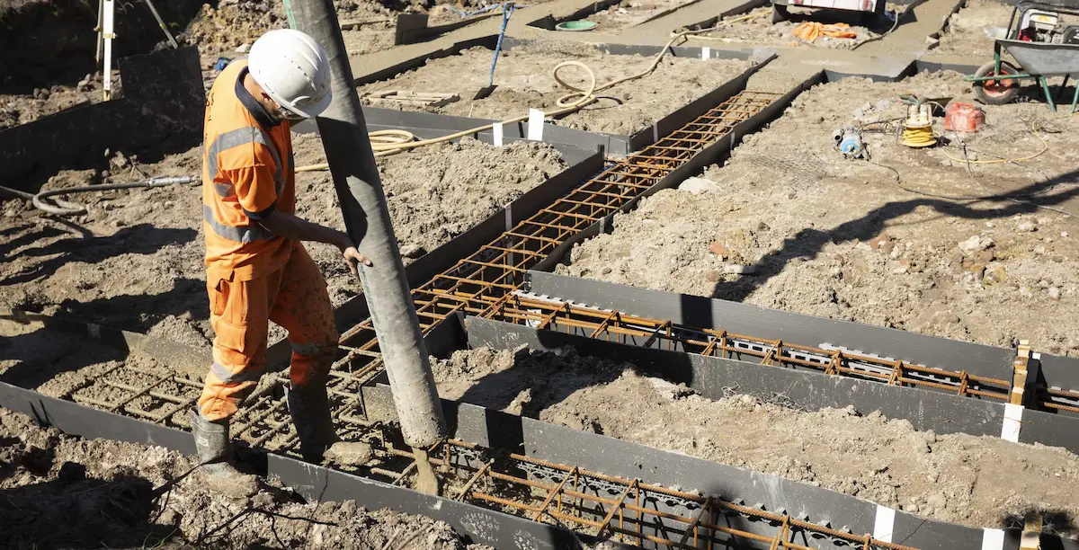
The concrete foundation is the main structure carrying the column overturning moment. It must strictly follow structural engineering specifications for reinforcement and pouring.
Concrete Strength Classes and Curing
●Strength Grade: The foundation concrete strength grade must not be lower than C30. For high-tonnage (5t and above) or high-frequency jib cranes, C35 or higher is recommended.
●Curing Period: The foundation must undergo sufficient curing after pouring is completed. Equipment installation and secondary grouting can proceed only after the concrete reaches 100% design strength.
Basic Dimensions and Reinforcement Requirements
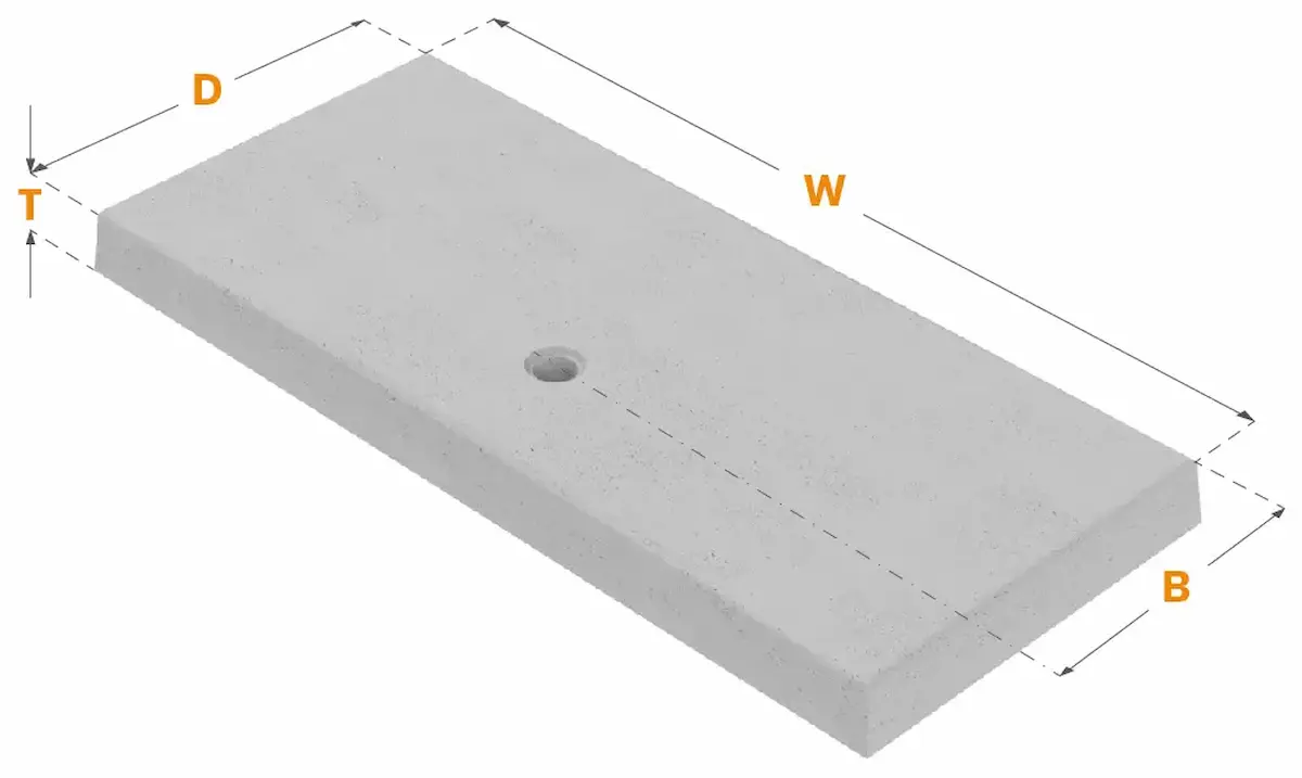
Foundation size is usually determined by anti-overturning calculations, forming a square or circular block.
|
Foundation Design Parameters |
Specification Requirements |
Description and Notes |
| Concrete Strength | >= C30 | Upgrade to C35 for large-tonnage equipment |
| Reinforcement Net | Double-layer bidirectional HRB400 | Upper and lower reinforcement nets must be fixed by tie bars |
| Protective Layer Thickness | >= 50mm | Ensure steel bars have good corrosion resistance and bond strength |
| Foundation Bearing Capacity | >= 150kPa | Soft foundations require piling or soil replacement treatment |
Anchor Bolt Selection, Layout, and Embedment Specifications
Anchor bolts are key connectors that anchor the column baseplate and concrete foundation together. Their design directly determines pull-out resistance.
Selection of Bolt Material and Quantity
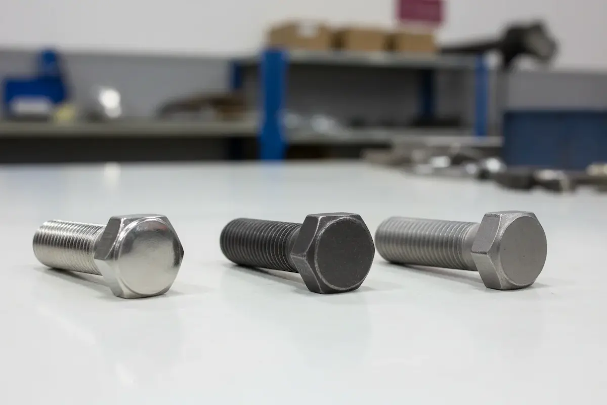
●Material Selection: High-strength bolts of Q345B or grade 45 steel are recommended. Ordinary Q235 mild steel is not recommended.
●Bolt Specifications and Layout: Bolts are usually evenly distributed around the column baseplate circumference. Bolt quantity and diameter are determined by maximum tensile force calculations. Each bolt must have double nuts and spring washers to prevent operational vibration loosening.
Comparison of Anchor Bolt Installation Methods
There are two main construction methods for pre-embedded bolts:
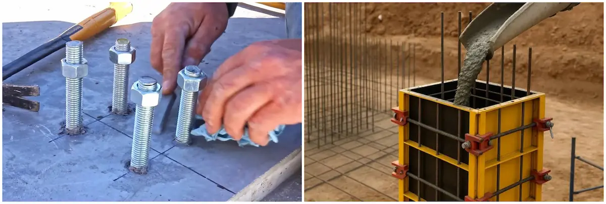
●Pre-embedded Bolt Group (Template Fixed): Before pouring, upper and lower locating plates weld and fix the bolt group in the steel cage. This method offers the best anchorage and high positioning accuracy, making it the preferred choice for jib cranes.
●Reserved Holes for Secondary Grouting: Bolt holes are reserved in the foundation, and bolts are inserted and grouted after equipment positioning. This method allows large adjustment margins, but high-strength non-shrink grout quality must be strictly ensured.
Jib Crane Foundation Construction and Installation Acceptance Essentials
Foundation construction quality directly determines subsequent equipment installation accuracy and service life.
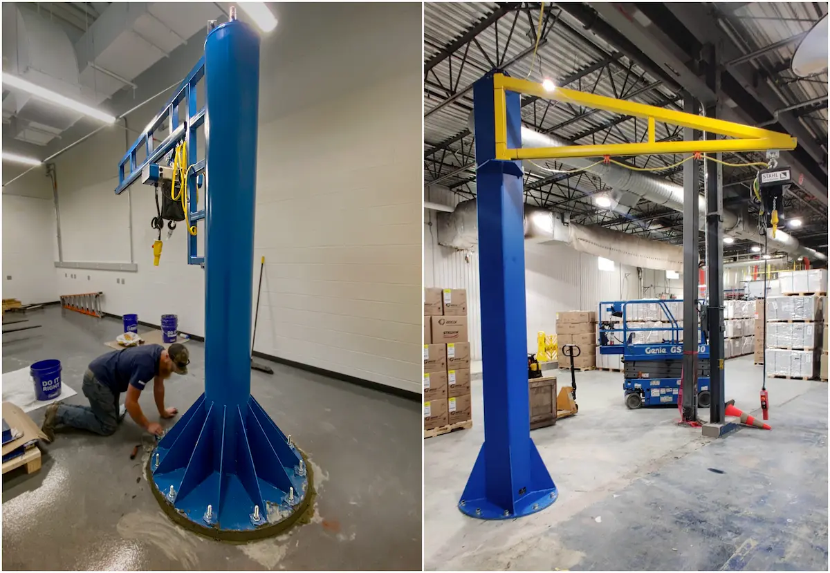
●Foundation Top Surface Flatness: A secondary grouting layer (typically 30-50mm) is reserved on top. Leveling shims adjust the column baseplate level during installation. Flatness error must be controlled within 1mm/m.
●Secondary Grouting: After the column baseplate is aligned, non-shrink high-strength grout must be used for secondary grouting. This ensures no voids or dead corners beneath the baseplate.
Summary and Recommendations
In summary, the design and construction of the jib crane foundation is a systematic engineering task. It directly relates to workshop operational safety and equipment service life. Every step matters, from precise force analysis of overturning moments and axial forces to strict concrete pouring. This includes standard reinforcement, high-strength anchor bolt matching, and precise embedment processes. Following these standards alongside precise secondary grouting builds a solid foundation system. It ensures the jib crane operates safely and efficiently during long-term high-intensity work.
This document is for reference only. Specific operations must strictly comply with local laws and regulations and equipment manuals.
Recent Post