Blog
- Home
- Blog
How to Choose the Slewing Angle for Jib Crane: Engineering & Layout Guide
In the jib crane selection process, the slewing angle determines the working radius coverage and the efficiency of the production line layout. Choosing an angle is not a matter of “the bigger, the better.” It requires technical justification based on factory structure, obstacles, and lifting cycle logic.
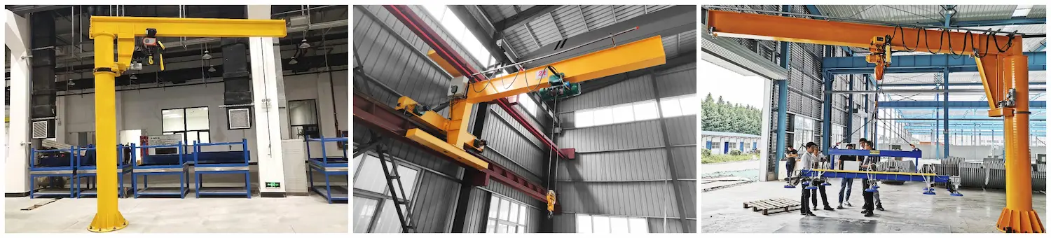
Core Classifications and Applications
Standard slewing angles are divided into 360° full rotation for pillar-mounted types and 180°/270° partial rotation for wall-mounted types.
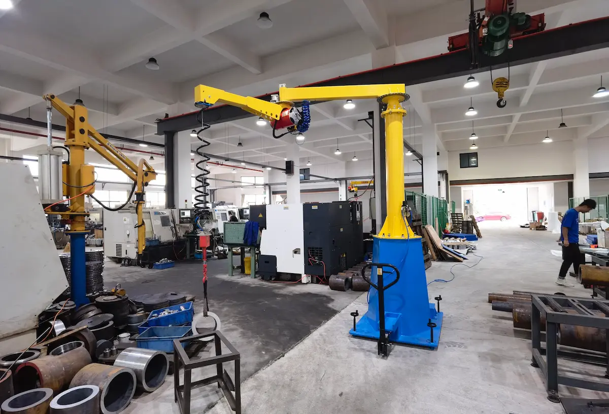
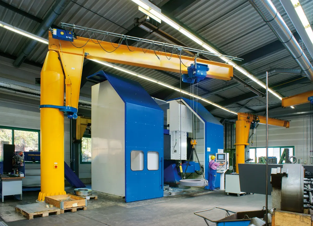
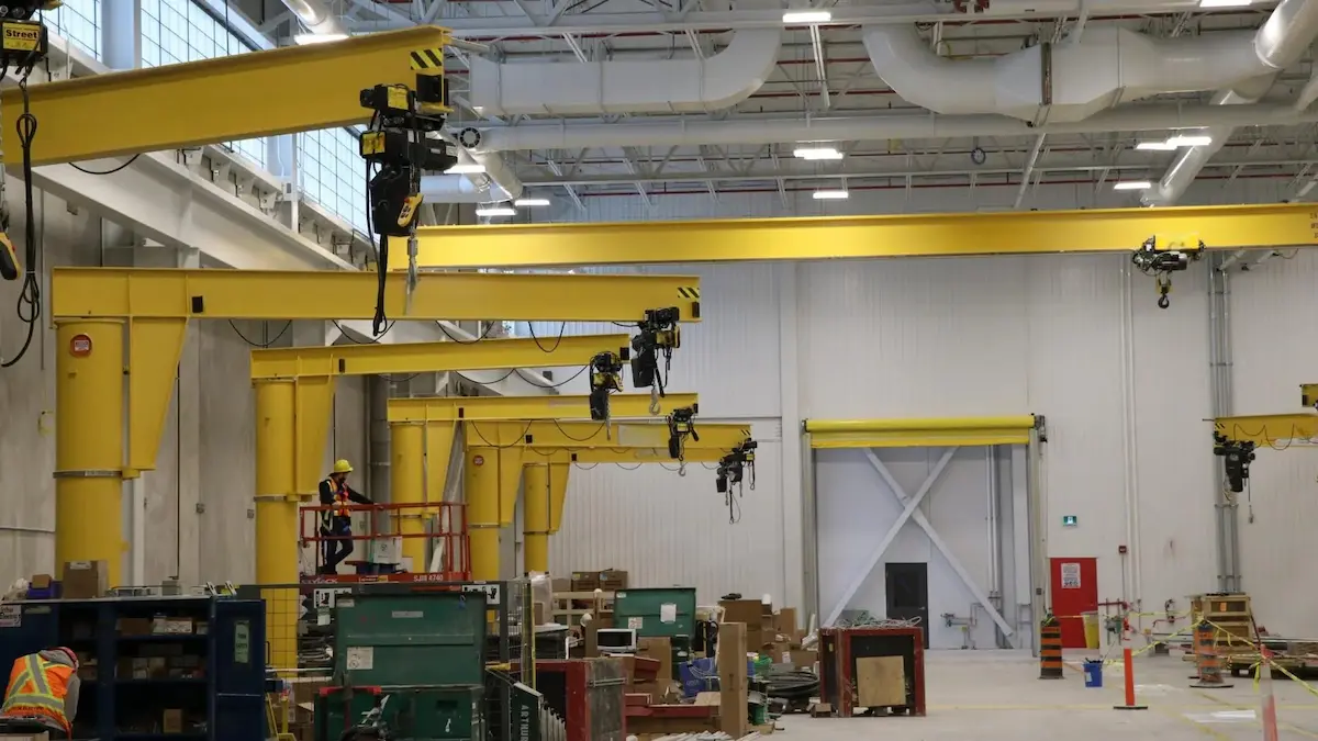
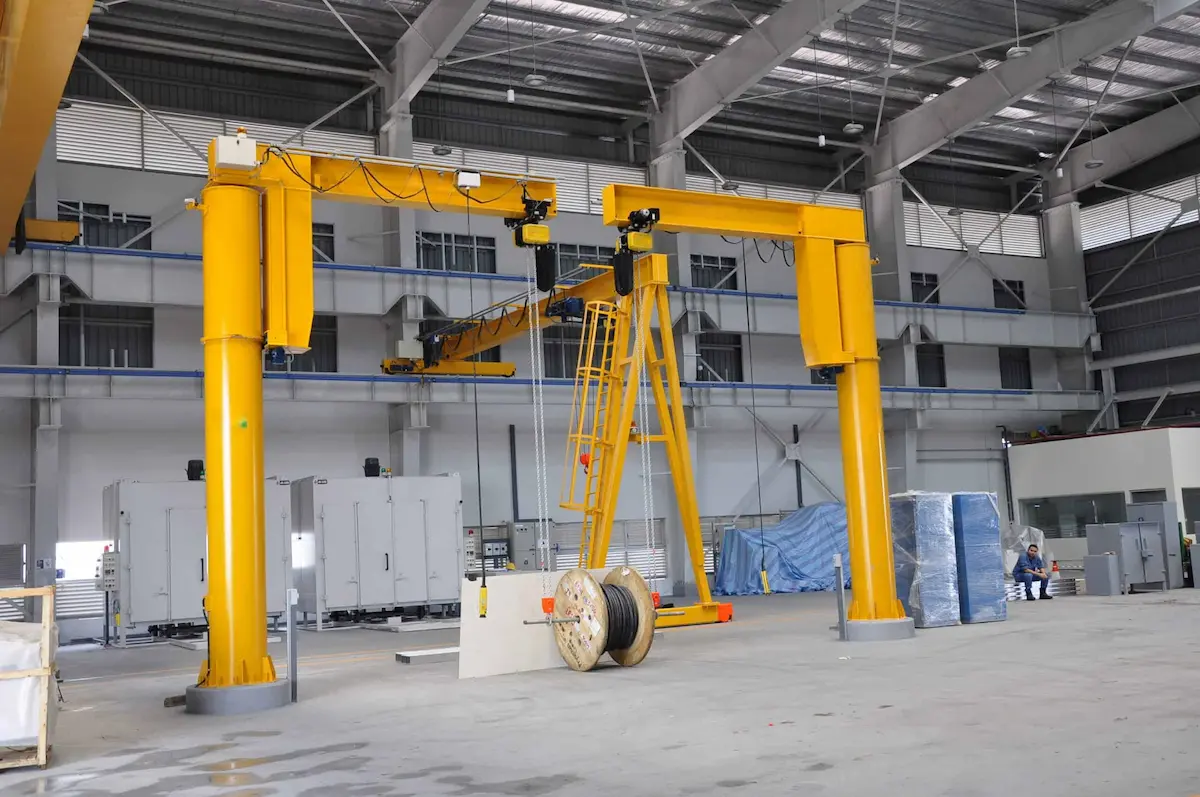
360° Pillar Mounted Jib Crane
●Engineering Features: Uses a slip ring for power supply to eliminate cable tangling and enable dead-zone-free operation.
●Applications: Center of independent work cells, open-air freight yards, and “center island” layouts requiring multi-station linkage.
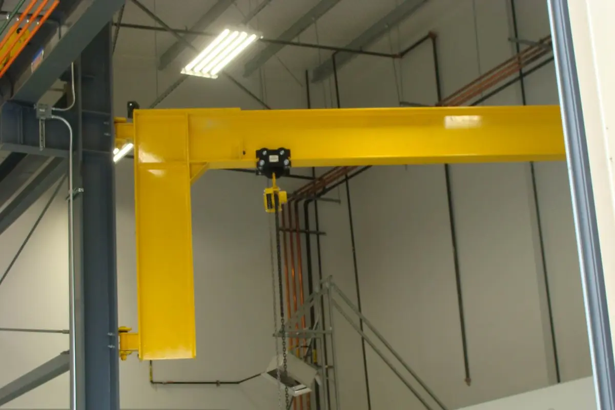
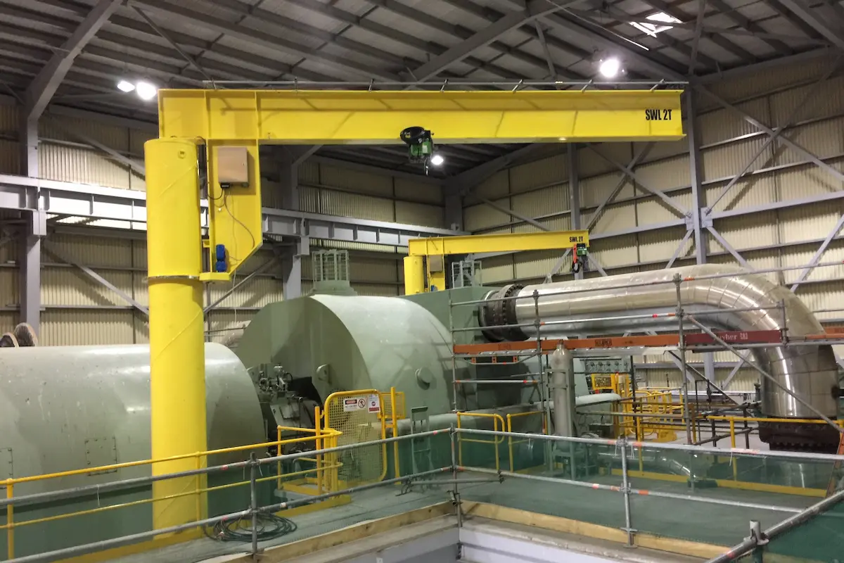
180° – 270° Wall Mounted Jib Crane
●Engineering Features: Rotation is limited by the building structure, such as support columns or walls.
●Applications: Operations close to walls or side stations in rectangular workshops.
Key Parameters Influencing Angle Selection
The engineering department must verify the following hard metrics before finalizing the crane angle:
●Structural Clearance and Obstacles: Verify that the jib path does not collide with columns, fire pipes, lighting busbars, or overhead cranes. For stations with physical barriers, install mechanical limits or programmable limit switches to lock the angle within a safe range.
●Coverage Redundancy: Target lifting points should fall within 80% of the maximum effective stroke. A narrow slewing angle increases alignment difficulty for operators and reduces work efficiency.
●Power Transmission Method
1. Manual Rotation: Usually unlimited. However, for loads over 2 tons or arm lengths exceeding 6 meters, electric rotation is recommended.
2.Electric Rotation: Braking distance must be considered. For high-inertia operations with large angles, a Variable Frequency Drive (VFD) is required to reduce physical impact.
Jib Crane Technical Specification Comparison
The following table provides an engineering reference for different rotation configurations:
|
Parameter |
180° Wall-Mounted |
270° Pillar-Mounted (with limiters) |
360° Pillar-Mounted |
| Support Method | Building walls / Concrete columns | Foundation flange | Foundation flange |
| Power Supply | Festoon system / C-track | Festoon system | Slip ring (Collector ring) |
| Slewing Mechanism | Self-lubricating bushings / Ball bearings | Heavy-duty slewing bearing | Heavy-duty slewing bearing |
| Typical Capacity | 0.125t – 5t | 0.5t – 10t | 0.5t – 20t |
| Space Utilization | Low (edge restricted) | Medium (focused coverage) | Very High (omni-directional) |
Optimizing Efficiency Through Slewing Angle
●Avoid “Over-Engineering”: If the workflow only involves linear movement (e.g., from conveyor A to pallet B), a 180° rotation with appropriate arm length is sufficient. This reduces slip ring maintenance and simplifies foundation design.
●Rotation Precision and Braking Control: In precision assembly, control accuracy is critical.
1.Pneumatic Rotation: Suitable for explosion-proof environments, offering soft angle control.
2.Servo Rotation: Used for automated docking, with angle errors controlled within ±0.5°.
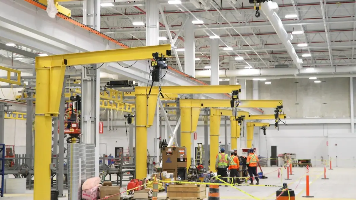
●Dual-Jib Redundancy Design: On long production lines, staggered 270° jib cranes offer more flexibility than a single ultra-long 360° unit. This setup distributes loads and prevents line shutdowns during single-unit maintenance.
Safety Limits and Engineering Protection
For non-360° rotation requirements, the following engineering measures must be taken:
●Physical Limit Pins: Weld blocks on the slewing support to prevent accidental collisions with factory walls.
●Electronic Fence Detection: Use proximity switches to sense rotation position. Power is automatically cut when the jib enters a non-working zone.
●Damping Adjustment: Regulate friction on the slewing shaft or motor braking force to prevent over-rotation caused by inertia.
Conclusion
The final logic for selecting a jib crane slewing angle should follow these rules: boundary constraints determine the limit angle, process paths determine the working angle, and foundation loads determine the structural form.
●Omni-directional tasks: 360° pillar-mounted is the preferred choice.
●Wall-side / Compact stations: 180° wall-mounted or 270° pillar-mounted is best.
●Multi-machine collaboration: Use segmented limiters to ensure working envelopes do not interfere with each other.
Unsure which rotation angle fits your workshop best?
The choice affects coverage, load verification, and safety limits. Contact our senior engineers for a free selection plan based on your CAD layout and a one-on-one technical quote.
[Get Your Free Selection Plan Now]
This document is for reference only. Specific operations must strictly comply with local laws and regulations and equipment manuals.
Recent Post